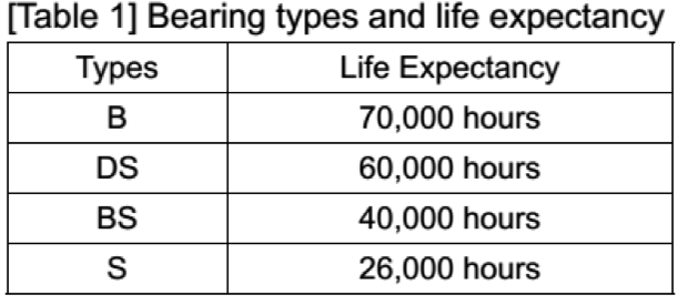
Bearing and Life
Life expectancy plays an important role when evaluating a fan’s performance. Then what is the crucial factor to life expectancy, the bearing system. Zaward has complete bearing options that fulfill different requirements from the application case by case. [Table 1] lists the bearing types and their life expectancy under the normal working environment.
Noise Level
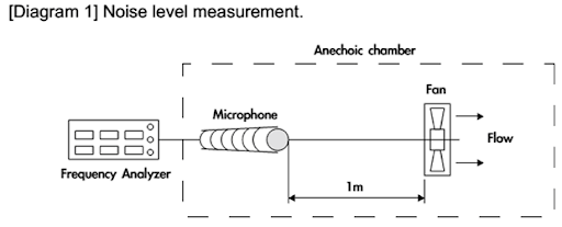
1. ACOUSTIC MEASUREMENT
The sound pressure level is measured in an anechoic chamber with a very quiet background. All sound pressure test conditions should follow ISO7779 standard. For normal situations, the microphone is positioned one meter from the air intake of the testing fan. It shall be hanged in clean air. Refer to [Diagram 1].
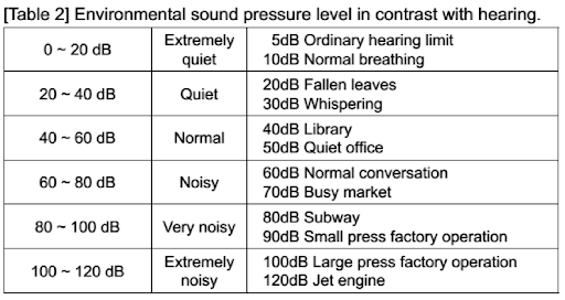
2. NOISE LEVEL [ Table 2]
3. SUPER LOW NOISE
Low noise is one of Zawards fan characteristics, especially in the Golf fan series. Its low flow turbulence of perfect 3-dimension impeller shapes and low flow resistance dimples surface design make the quieter rotation and more effective heat dissipation.
4. HOW TO REDUCE THE NOISE LEVEL
Low noise is one of Zawards fan characteristics, especially in the Golf fan series. Its low flow turbulence of perfect 3-dimension impeller shapes and low flow resistance dimples surface design make the quieter rotation and more effective heat dissipation.
4.1 System impedance
The airflow resistance from the computer systems or equipment is called system impedance. For the blow-in system, the total area measure of the air outlet needs to be 20% ~ 40% larger than that of the air intake. As for the blow-out system, the total area measure of air intake needs to be 20% ~ 40% larger than that of the air outlet. If the air outlet of the blow-in system or the air intake of the blow-out system is too small, it brings more system impedance which causes poorer heat dissipation. By increasing the fan speed to enlarge the airflow, the noise level will be higher.
By adjusting the area of the air intake and the air outlet the system impedance can be reduced, and the noise level will be lowered at the same time. This is also helpful for the proper arrangement of the system’s components.
But if the air outlet of the blow-in system or the air intake of the blow-out system is too wide, the airflow speed will be too low. Thus, it is unable to bring out the heat of the components efficiently. The wider space inside the system makes less flow impedance. The heat dissipation is better if the heat source components located properly on the way of airflow.
4.2 Flow turbulence
The vertical barrier and sharp angle shapes in the airflow passage will cause noise. Therefore, we need to prevent these structures, particularly on the main air intake and outlet areas that have higher airspeed. Zaward’s fans are with the curve-edged design on the air intake and outlet to minimize the flow turbulence enabling to accelerate the airflow blowing in and out.
4.3 Fan speed and size
The high-speed fan makes a higher noise level than that at low speed. Thus, it is recommended to use the fan with low speed if possible. With the same airflow,
the fan in bigger size and lower speed is quieter than that in smaller size and higher speed.
4.4 Temperature rise
In a system, the required cooling airflow is with the inverse ratio against the allowable temperature rise. Slight temperature rise reduces airflow tremendously. Therefore, if the allowable temperature rise is slightly lowered, the airflow will be decreased and the noise level will be significantly reduced as well.
4.5 Fan fixing components
Component design of fan fixing relates to the system noise level. Thus, it’s essential to selects anti-vibration materials while fix the fan or assembly the fan on your chassis. If special low noise design is required, please contact our sales department.
Airflow
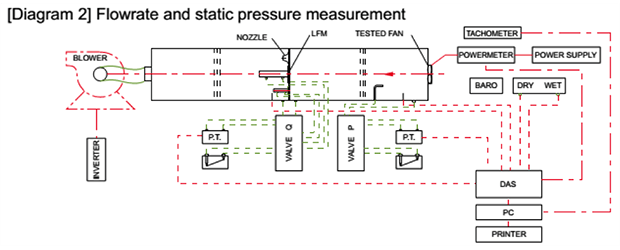
1. FLOW RATE AND STATIC PRESSURE
The measurement of flow rate and static pressure is easily affected by various factors, so we need to apply precise measurement instruments including automatic pneumatic tunnel apparatus is made in accordance with the international standard of AMCA210. Its measuring range covers flow rate 3 ~ 250 CFM, static pressure 0 ~ 60 mmAq. See [diagram 2]
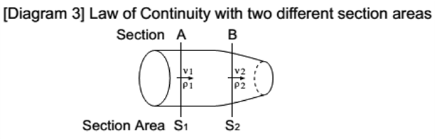
2. TEST THEORY: LAW OF CONTINUITY
The continuity of flow equation is one of the major tools of fluid mechanics that provides a means to calculate the velocities at different points in a system. For steady flow in a stream tube, having a changeless cross-sectional area over any given cross-section, the mass flow per unit time will be equivalent. Then ρνS will be a Constant. Suppose that there are two different sections A and B in the stream tube.
In section A the cross-sectional area is S1, and its flow velocity is V1, and its density is ρ1.
In section B the cross-sectional area is S2, and its flow velocity is V2, and its density is ρ2.
Then ρ1V1S1 = ρ2V2S2 = Constant. As the flow can be considered as incompressible and ρ1=ρ2, therefore V1S1 = V2S2.
2.1 Adjust the auxiliary blower makes static pressure come to zero.
It gets the maximum flow rate point Qmax.
2.2 Shut down the auxiliary blower makes the flow rate come to zero.
It gets the maximum static pressure point Pmax.
2.3 Adjust different flow rate points of blower to get PQ curve.
To measure different flow rate points needs to adjust the nozzle’s diameter. The pressure difference caused between the front and rear chambers of nozzle. Its pressure difference measured from the instrument needs to transfer from the computer. Use the law of continuity, the variety of pressure difference can achieve equivalent air speed and flow rate (flow rate = air speed x nozzle’s section area).
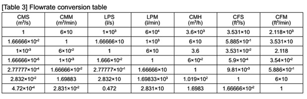
2.4 Flow rate conversion table [table 3]
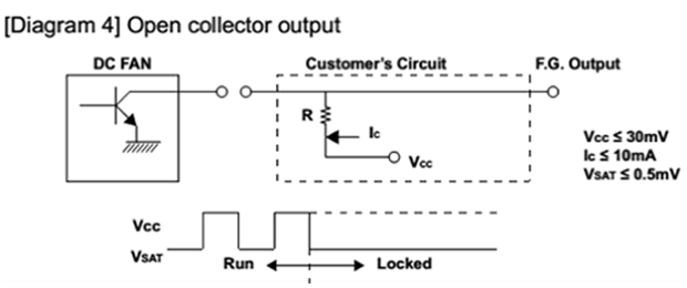
Speed
There are various ways to measure the fan rotation speed, such as using oscilloscope, stroboscope, infrared, fans open collector output as shown in diagram 4, and use a third lead wire to output a square wave.